Engineering Guide: Root Cause Analysis and Troubleshooting Solutions for Parting Line Flash
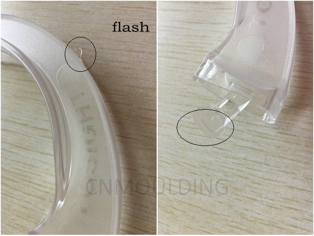
In precision plastic injection molding, flash (also referred to as burrs or air slits) is a critical defect where molten polymer escapes the intended mold cavity via the parting line, venting slots, or ejector pin clearances. Flash compromises dimensional tolerances, cosmetic specifications, and mechanical functionality.
To eliminate flash, engineers must systematically evaluate the interaction between tooling integrity, machine dynamics, and process parameters. Below is a comprehensive engineering analysis and troubleshooting guide.
1. Tooling Integrity & Mold Design Optimization
The mechanical sealing of the parting surface is the primary defense against flash. Any deflection or misalignment under high injection pressure will result in material leakage.
- Parting Line Interferences and Mismatch: Inspect the mold parting surfaces for deformation, crushed edges, or embedded foreign debris. Debris or localized crushing prevents the mold halves from sealing completely.
- Structural Deflection: Insufficient support pillars or thin mold plates can cause backing plates to flex under high cavity pressure. Ensure robust support structures within the mold base to minimize tool breathing.
- Material Selection and Hardness: Utilizing low-grade steels for core/cavity inserts accelerates parting line wear. For long production runs, utilize high-quality pre-hardened or hardened tool steels (e.g., JIS S50C for standard bases, or HRC 50+ hardened tool steels like H13 or 718H for cavities/cores) to maintain sharp parting edges and resist compressive deformation.
- Venting Depth Specifications: Venting is required to evacuate displaced air, but excessive vent depths allow polymer to enter. Verify that venting depths conform to material specifications (e.g., 0.015–0.02 mm for low-viscosity crystalline polymers like PA66; up to 0.03–0.05 mm for amorphous, high-viscosity polymers like PC or ABS).
2. Injection Molding Process Parameter Optimization
When tooling is verified, process parameters must be balanced to ensure the cavity is filled without over-pressurizing the parting line.
- Injection Velocity and Pressure Profile: Excessive injection speed causes a sharp spike in peak cavity pressure, which can momentarily force the mold open (“mold breathing”). Optimize the velocity-to-pressure (V-P) switchover point to transition to holding pressure at 95–98% volumetric fill. Delayed V-P switchover overpacks the cavity, directly causing flash.
- Melt and Mold Temperature Control: Excessively high melt or mold temperatures drastically reduce polymer viscosity, enabling the material to easily penetrate clearances as small as 0.01 mm. Lower the barrel temperature zones and optimize coolant flow to stabilize melt rheology.
- Clamp Tonnage Calibration: Insufficient clamping force allows the dynamic pressure of the melt to separate the mold halves. Verify that the machine’s rated clamp tonnage exceeds the calculated required tonnage (Projected Area of the Part and Runner $\times$ Average Cavity Pressure). Note: Conversely, excessively high clamping pressure can compress and permanently deform the parting surface edges, accelerating future flash issues.
3. Evaluation of Secondary Solutions and Post-Processing
- Mold Release Agents (Interim Control): While release agents facilitate part ejection, they should not be relied upon to fix flash. Improper application can alter surface cosmetics or cause gas traps. Their primary function is friction reduction during ejection, not gap sealing.
- Post-Molding Deflashing Operations: For legacy tooling where modification is cost-prohibitive, manual deflashing (trimming, scraping, or micro-sanding) can be implemented. However, this introduces manual labor variables, increases cycle cycle-to-cycle variance, and drives up the total cost of quality (COQ).
- Automated Deflashing Equipment: For high-volume production with unavoidable flash, automated options such as robotic trimming cells, cryogenic deflashing, or CNC finishing provide superior consistency and lower per-part cycle times compared to manual rework.
Engineering Troubleshooting Matrix
| Root Cause Category | Diagnostic Check | Corrective Action |
| Tooling | Parting line inspection | Remove debris; rework/re-grind parting surfaces to ensure 100% blue-layout contact. |
| Tooling | Venting check | Measure vent depth; reduce depth if it exceeds material flash-limit thresholds. |
| Process | V-P Switchover point | Adjust V-P switchover earlier to prevent cavity overpacking. |
| Process | Viscosity management | Lower melt and mold temperatures to reduce fluid capillary action at parting lines. |
| Machine | Clamp Tonnage | Calculate projected area; increase machine clamping force within safe tooling limits. |