Technical Whitepaper: Precision Tooling Design, Thermal Optimization, and Gas-Assisted Injection Molding
1. Plastic Injection Mold Engineering & Tooling Paradigms
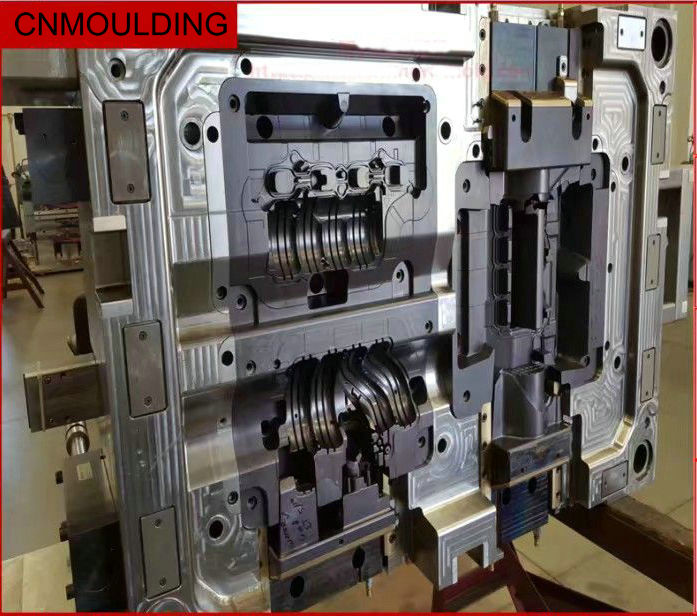
The injection molding process demands precise thermodynamic control to produce high-quality, thin-walled plastic parts with high dimensional accuracy. At CNMOULDING, when a 3D CAD design is received from a customer, our engineering team immediately initiates Design for Manufacturing (DFM) protocols.
To ensure tool longevity and export-quality reliability, we build tools using premium certified steels (such as P20, S136, NAK80, or H13) processed via high-speed 5-axis CNC and mirror EDM. This technical execution supports high-compliance global sectors, including Automotive (dashboards, structural trims), Consumer Electronics (thin-walled enclosures), and Medical Devices (fluid control valves, syringes under ISO 13485).
2. Tool Thermal Dynamics: Optimizing Cooling Efficiency
A precisely engineered cooling system is critical to prevent thermal warpage, control residual stress, and compress cycle times. Rather than relying on guesswork, our tooling designs are backed by strict thermodynamic verification.
Core Thermodynamic Engineering Workflow:
- Melt Heat Input (Q): We calculate the total thermal energy introduced into the mold cavity per hour based on part mass (0.051kg/shot), resin specific heat capacity, and melt temperature (Q1 = 200°).
- Energy Evacuation (Q_w): To maintain thermal equilibrium, the cooling circuit is engineered to evacuate approximately 95% of this thermal load through continuous fluid circulation.
- Flow Dynamics (h_w): Using the empirical Dittus-Boelter adaptation, we calculate the ideal fluid velocity (1.66\text{ m/s}) to transition the cooling water from laminar to turbulent flow. This maximizes the heat transfer coefficient (h_w = 3863.9 { W/m2K).
Engineering Action & Implementation
Based on these thermodynamic calculations for thin-walled components, we eliminate localized hot spots and optimize cycle efficiency by deploying a balanced layout of $\varnothing 8\text{mm}$ cooling lines with brass-interconnected waterways uniformly across both the core and cavity inserts.
3. Gas-Assisted Injection Molding (GAIM) & CAE Simulation
Gas-Assisted Injection Molding (GAIM) represents a major milestone in high-tier plastic processing, developed to overcome the physical limitations of conventional molding when handling large, structural, or variable-wall geometries.
By injecting a precise volume of pressurized Nitrogen gas ($N_2$) into the molten polymer core, we create internal hollow networks that pack the plastic against the cavity walls from the inside out.
Key Engineering Advantages of GAIM:
- Zero Sink Marks: Continuous internal gas pressure compensates for polymer contraction in thick sections, ensuring flawless surface profiles.
- Minimized Warpage: Significantly lower injection pressures drastically reduce molded-in residual stress.
- Material & Weight Savings: Hollow cross-sections reduce part weight and material consumption while increasing structural rigidity.
Defect Prevention via Advanced CAE Simulation
Because gas behavior inside a shifting polymer melt is dynamic, we utilize advanced CAE simulation software (such as Autodesk Moldflow) before cutting steel to prevent critical molding defects:
- Gas Breakthrough Prevention: We balance the polymer-to-gas delay timer to ensure the nitrogen core never ruptures or penetrates the thin-walled surface.
- Short Shot Control: We pinpoint the exact initial plastic melt volume required so that secondary gas expansion fills the cavity perfectly without causing flash.
- Gating & Gas Road Optimization: We verify the ideal positions for polymer injection gates, gas injection pins, and gas channel geometries based on rigorous numerical analysis.