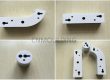
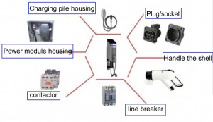
Metal inserts are widely used in new energy vehicle (NEV) components where mechanical fastening, electrical insulation, structural reinforcement, or dimensional stability is required. Typical applications include battery pack components, busbar assemblies, structural brackets, threaded inserts, and other metal-plastic components.
Metal insert molding combines a metal insert with an engineering plastic in a single injection molding process. This can reduce assembly operations and improve component integration, but it also introduces several manufacturing challenges.
The main risks are related to insert positioning, metal-plastic thermal stress, insert retention, and mold design. These issues need to be considered during the part design and DFM stage rather than being addressed only after mold fabrication.
3 Common Challenges in Automotive Insert Molding
1. Insert Displacement During Injection
During the filling and packing stages of injection molding, the flow of molten plastic can generate significant forces around the metal insert. If the insert is not adequately supported, it may move, rotate, or tilt inside the cavity.
Even a small positional deviation can affect thread alignment, assembly dimensions, wall thickness, or the relationship between the insert and surrounding plastic features. In some cases, an incorrectly positioned insert can also interfere with mold components and increase the risk of tooling damage.
How We Address It
Insert positioning is considered as part of the mold design from the beginning.
Depending on the insert geometry and production requirements, we may use:
- Precision insert locating pockets
- Mechanical locating pins and supports
- Dedicated core features around the insert
- Appropriate clearance and shut-off design
- Automated insert loading for high-volume production
- Vision-based positioning where tighter positioning control is required
The objective is not simply to hold the insert in place, but to establish a repeatable positioning method that remains stable throughout the molding cycle.
For high-volume automotive programs, the insert loading process can also be reviewed together with the mold design to improve cycle consistency and reduce operator-dependent variation.
2. Thermal Stress Between Metal and Plastic
Metal and engineering plastics have different thermal expansion and shrinkage characteristics. During injection molding, the polymer melt enters the cavity at a much higher temperature than the metal insert. As the part cools, the plastic and metal respond differently to the temperature change.
This difference can create residual stress around the insert.
If the stress is concentrated by sharp corners, thin plastic sections, or an unsuitable insert geometry, it may contribute to cracking, deformation, or reduced interface performance during subsequent thermal cycling.
For NEV applications, these effects can become particularly important when components are exposed to repeated temperature changes or require tight dimensional control.
How We Address It
Thermal behavior is considered during both material selection and mold development.
Depending on the resin, insert geometry, and required performance, the process may include:
- Appropriate insert preheating
- Controlled mold temperature
- Optimized filling and packing conditions
- Controlled cooling
- Suitable plastic wall thickness around the insert
- Stress-relief features in the part design
- Evaluation of glass-fiber orientation and molding shrinkage
Insert preheating is not treated as a fixed process parameter. The appropriate temperature and process window depend on the resin, metal insert, component geometry, and performance requirements.
For demanding applications, molding trials and thermal cycling tests can be used to verify the design rather than relying only on theoretical calculations.
3. Insert Retention and the Metal-Plastic Interface
A smooth metal surface does not automatically provide sufficient mechanical retention after injection molding. Depending on the application, the insert may be exposed to pull-out forces, torque, vibration, thermal cycling, or repeated assembly loads.
For this reason, the interface between the metal insert and plastic should be considered during the early design stage.
How We Address It
Where appropriate, the metal insert can be designed with mechanical retention features such as:
- Knurling
- Circumferential grooves
- Undercuts
- Slots or other retention features
These features allow the plastic to mechanically lock around the insert and can improve pull-out and torque resistance.
The mold design must also provide sufficient support and appropriate plastic flow around the insert. Gate location, venting, packing conditions, cooling, and local wall thickness can all affect the final interface quality.
For applications that require sealing or leak-tight performance, the sealing function should be treated as a specific design and validation requirement rather than assumed from mechanical interlocking alone.
Material Selection for NEV Insert Molding
The plastic material should be selected according to the actual electrical, thermal, mechanical, dimensional, and flame-retardant requirements of the component.
Depending on the application, engineering plastics such as PBT, PPS, PA, and their reinforced or flame-retardant grades may be considered.
For example, glass-fiber-reinforced materials can provide improved stiffness and dimensional stability, but the glass-fiber content and flow direction can also affect:
- Molding shrinkage
- Warpage
- Fiber orientation
- Local mechanical properties
- Dimensional accuracy around the insert
- Residual stress
Therefore, material selection should not be based on flame retardancy alone.
The resin grade, reinforcement level, processing requirements, insert material, part geometry, and final application conditions all need to be considered together.
What We Review During Insert Molding DFM
A reliable insert molding process starts before the injection mold is built.
During the DFM stage, we review the relationship between the metal insert, plastic component, and mold structure.
Insert Design
We review:
- Insert dimensions and tolerances
- Knurling, grooves, or undercuts
- Required pull-out and torque performance
- Insert loading direction
- Potential interference with mold components
Plastic Part Design
We evaluate:
- Wall thickness around the insert
- Ribs and bosses
- Stress concentration areas
- Draft angles
- Shrinkage and warpage risks
- Plastic flow around the insert
Mold Design
The mold design may include:
- Insert locating and supporting structures
- Core and cavity clearances
- Gate location
- Venting
- Cooling layout
- Hot runner or cold runner configuration
- Mold protection considerations
Injection Process
The molding process is then developed around the actual material and component requirements, including:
- Insert temperature
- Mold temperature
- Filling conditions
- Packing pressure and time
- Cooling conditions
- Part ejection
- Dimensional control
This integrated approach helps identify potential problems before they become tooling or production problems.
From Insert Design to Stable Mass Production
Insert molding is not simply a matter of placing a metal component into an injection mold. The insert, plastic material, part geometry, mold structure, and molding process all influence the final result.
For NEV components, these factors should be considered together from the beginning of the project.
Our engineering team can support customers through the process from insert and part design review to mold development, trial molding, process optimization, and mass production.
The goal is to develop a molding process that is not only capable of producing the first qualified sample, but also remains consistent during long-term production.
Planning an NEV Component with Metal Inserts?
Share your part drawing, material requirements, insert configuration, and production requirements with our engineering team.
We can review the component structure and identify potential risks related to insert positioning, material selection, mold design, thermal stress, and injection molding during the DFM stage.
Request an Insert Molding DFM Review