Understanding injection molding terminology is important when developing a new plastic part or communicating with an injection mold manufacturer.
This guide explains commonly used terms in plastic injection molding, injection mold design, and mold manufacturing. The definitions are written from a manufacturing perspective, with a focus on how each term affects part design, mold structure, tooling cost, and production.
Injection Molding Terms
Part
A part is the plastic component produced by the injection molding process.
The part is normally defined by the customer’s 2D drawing, 3D CAD model, specification, or physical sample. Part geometry, material, dimensional tolerances, surface finish, and annual production volume directly affect the injection mold design.
Injection Mold / Tool
An injection mold, also called a tool, is the precision mold used to form the plastic part.
The mold contains the cavity, core, runner or hot runner system, cooling channels, and ejection system. Mold construction is determined by the part geometry, plastic material, production volume, and required mold life.
Shrinkage
Plastic shrinkage is the dimensional reduction that occurs as the molten plastic cools and solidifies.
Different plastics have different shrinkage characteristics. For example, polypropylene, ABS, polycarbonate, nylon, and POM require different shrinkage considerations during mold design.
Shrinkage is normally compensated for in the mold dimensions. For critical dimensions, the mold may be designed with steel safe so that dimensions can be adjusted after the first molding trials.
Material selection should therefore be confirmed before finalizing critical mold dimensions.
Gate
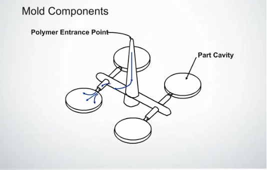
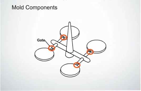
The gate is the opening through which molten plastic enters the mold cavity.
Gate design affects filling behavior, injection pressure, weld lines, packing, cycle time, and gate vestige.
Common injection molding gate types include:
- Edge gate
- Fan gate
- Pin gate
- Sub gate
- Direct gate
- Hot runner gate
- Valve gate
The appropriate gate location depends on the part geometry, material, appearance requirements, and filling conditions.
Gate Vestige
Gate vestige is the small mark or remaining material left on the molded part after the gate is separated from the part.
For cosmetic components, gate location and vestige size should be considered during mold design. Where necessary, the gate can be positioned in a non-visible area or a gate type can be selected to minimize the visible mark.
Runner
A runner is the passage that carries molten plastic from the sprue or hot runner system toward the mold cavity.
A conventional cold-runner mold uses solidified runners that are ejected with the molded parts. A hot runner mold keeps the material molten inside heated components, reducing or eliminating cold runner waste.
Runner size and layout affect filling pressure, material consumption, cycle time, and filling balance.
Hot Runner
A hot runner system uses heated manifolds and nozzles to deliver molten plastic directly toward the mold cavity.
Hot runners can reduce runner waste and may improve production efficiency, especially for high-volume production.
However, hot runner molds require appropriate temperature control, component selection, maintenance, and processing parameters.
Sprue
The sprue is the main passage through which molten plastic enters the mold from the injection molding machine nozzle.
In a conventional cold-runner mold, the sprue connects the machine nozzle to the runner system.
Ejector Pin
An ejector pin is a mold component used to push the molded plastic part away from the core after the mold opens.
Ejector pin locations should be selected according to the part geometry and ejection requirements. Improper ejector placement can cause deformation, visible ejector marks, or difficulty during ejection.
Undercut
An undercut is a feature that prevents the molded part from being removed directly from the mold in the opening direction.
Typical undercuts include side holes, internal hooks, retaining features, and side slots.
Depending on the geometry, an undercut may require a slider, lifter, collapsible core, or other mold mechanism.
Slider
A slider is a movable mold component used to form a side feature or undercut.
The slider moves laterally during the mold opening and closing sequence, allowing the molded part to be released without damaging the undercut feature.
Sliders are commonly driven by an angle pin, hydraulic cylinder, or other mechanical mechanism depending on the mold design.
Lifter
A lifter is an angled or moving ejection component commonly used to form and release internal undercuts.
Lifters are frequently used for features such as internal hooks, snap fits, and other areas that cannot be released with conventional straight ejector pins.
Angle Pin / Cam Pin
An angle pin, sometimes called a cam pin, is commonly used to actuate a mold slider.
As the mold opens, the angle pin drives the slider backward or forward to release the side undercut. The angle, stroke, clearance, and slider locking arrangement must be considered during mold design.
Gib / Wear Plate
A gib or wear plate is a mold component used to guide and support moving components such as sliders.
Proper guidance and wear protection are important for maintaining smooth slider movement and extending mold service life.
Core
The core is the mold component that forms the internal or recessed geometry of the plastic part.
In many injection molds, the core is located on the moving half of the mold and the molded part remains on the core side when the mold opens.
However, the exact mold configuration depends on the part geometry and mold design.
Cavity
The cavity is the mold surface that forms the external or visible geometry of the plastic part.
A mold may contain one cavity or multiple cavities depending on the required production volume and mold configuration.
For example, a four-cavity mold produces four molded parts during each injection cycle.
Parting Line
The parting line is the interface where the two main mold halves meet.
Parting line design affects part appearance, flash control, mold manufacturing, ejection, and the ability to release the molded part.
For cosmetic parts, the parting line should normally be positioned in an area where it has minimal visual and functional impact.
Core Out
Core out means removing unnecessary material from a thick section of a plastic part to achieve a more uniform wall thickness.
Core-out design helps reduce:
- Sink marks
- Warpage
- Material consumption
- Cooling time
- Molding cycle time
Instead of designing a solid thick section, engineers often use ribs, bosses, and core-out features to maintain structural strength while controlling wall thickness.
Steel Safe
Steel safe is additional mold steel intentionally left in a critical area so that the dimension can be adjusted during mold trials.
For example, if a critical feature is expected to require dimensional adjustment, the mold maker may leave extra steel instead of machining directly to the final theoretical dimension.
It is generally easier to remove steel during mold modification than to add steel back to a finished mold.
Draft Angle
A draft angle is a slight taper applied to vertical surfaces of an injection molded part to allow the part to release from the mold.
Insufficient draft can cause:
- Ejection problems
- Scratches
- Drag marks
- Part deformation
- Mold damage
The required draft angle depends on the material, surface texture, part depth, and mold finish.
Wall Thickness
Wall thickness refers to the thickness of the plastic section of a molded part.
Consistent wall thickness generally provides more predictable filling and cooling.
Large variations in wall thickness can increase the risk of:
- Sink marks
- Warpage
- Uneven shrinkage
- Internal stress
- Longer cooling time
Wall thickness should therefore be considered during DFM before the mold is manufactured.
Thin-Wall Injection Molding
Thin-wall injection molding refers to molding plastic components with relatively thin wall sections compared with their overall dimensions.
Thin-wall parts usually require careful control of:
- Injection speed
- Injection pressure
- Material flow
- Mold temperature
- Venting
- Gate design
- Cooling
The practical minimum wall thickness depends on the material, flow length, part geometry, and molding machine. A fixed value should not be applied to every project.
Boss
A boss is a raised cylindrical feature on a plastic part, typically used for screws, locating pins, inserts, or assembly features.
Boss diameter, wall thickness, height, draft, and connection to surrounding walls should be considered to reduce the risk of sink marks and cracking.
Rib
A rib is a thin reinforcing feature molded into a plastic part.
Ribs increase structural stiffness without requiring a large increase in overall wall thickness.
Proper rib thickness and height are important because overly thick ribs can create sink marks and uneven cooling.
Sink Mark
A sink mark is a visible depression on the surface of a molded plastic part caused by localized shrinkage.
Sink marks are commonly associated with:
- Thick wall sections
- Thick bosses
- Thick ribs
- Insufficient packing
- Poor cooling conditions
Part geometry should be optimized during DFM before attempting to solve sink marks only through molding parameters.
Warpage
Warpage is unwanted deformation or distortion of a molded plastic part after molding.
Warpage can result from uneven shrinkage, non-uniform wall thickness, fiber orientation, unbalanced filling, uneven cooling, or inappropriate processing conditions.
Mold design, cooling system design, material selection, and processing parameters all influence warpage.
Shear
Shear occurs when the plastic melt experiences deformation as it flows through the injection molding system.
Excessive shear can increase melt temperature and may cause material degradation, burning, or other molding defects.
Shear should be considered when designing gates, runners, and processing conditions, especially for shear-sensitive materials.
Slider Action
Slider action refers to the movement of a slider or other side-action mechanism used to release an undercut from the mold.
If the part design contains side holes, hooks, slots, or other undercuts, the mold may require a slider or lifter mechanism to complete the molding cycle.
Heel Block
A heel block is a support component used to resist the injection pressure acting on a mold slider.
It helps prevent the slider from being pushed backward during injection and provides additional support to the side-action mechanism.
Rapid Prototyping
Rapid prototyping is the process of producing a physical prototype directly from a 3D CAD model before committing to production tooling.
Prototypes can be produced using technologies such as SLA, FDM, SLS, or other additive manufacturing processes.
Rapid prototypes are useful for checking:
- Product fit
- Assembly
- Ergonomics
- Appearance
- Basic functional requirements
A prototype, however, does not always reproduce the same material properties or surface characteristics as an injection molded production part.
SLA
SLA (Stereolithography) is an additive manufacturing process that uses light to cure liquid photopolymer resin layer by layer.
SLA is commonly used for prototypes requiring relatively high dimensional accuracy and fine surface detail.
FDM
FDM (Fused Deposition Modeling) is a 3D printing process in which thermoplastic filament is heated and deposited layer by layer.
FDM is commonly used for functional prototypes, fixtures, concept models, and early-stage product evaluation.
Mold Operator
A mold operator or injection molding operator is responsible for operating the injection molding machine and monitoring the molding process.
Typical responsibilities include machine operation, part inspection, material handling, trimming, packaging, and reporting molding abnormalities.
Bulk Packing
Bulk packing means molded plastic parts are packed together in boxes, bags, or containers without individual protective packaging.
Bulk packing is commonly used for durable industrial plastic components where individual protection is not required.
Packaging requirements should be confirmed according to the part geometry, surface finish, transportation method, and customer requirements.
Reverse Engineering
Reverse engineering is the process of analyzing an existing physical part and recreating its geometry as a digital 3D model.
The process may involve dimensional measurement, 3D scanning, CAD reconstruction, and DFM review.
Reverse engineering can be useful when the original CAD data is unavailable and a replacement or modified injection molded part needs to be developed.
Injection Mold Design Starts With the Part
A reliable injection mold begins with a manufacturable part design.
Before mold construction, our engineers review the customer’s 3D model or drawing for:
- Wall thickness
- Draft angle
- Undercuts
- Rib and boss design
- Parting line
- Gate location
- Ejection
- Shrinkage
- Cooling
- Surface finish
- Dimensional tolerances
This DFM review helps identify potential molding problems before steel is cut.
Professional Injection Mold and Plastic Injection Molding Manufacturer
We are a China-based injection mold manufacturer and plastic injection molding supplier, providing mold design, mold manufacturing, injection molding, sampling, inspection, and production support.
Our engineering approach is focused on production reliability. We consider not only whether a mold can produce the first sample, but also whether the mold can maintain stable performance during long-term production.
If you have a plastic part drawing, 3D CAD model, or physical sample, our engineers can review the design and evaluate the appropriate injection mold structure and plastic injection molding process for your project.