Troubleshooting and Preventing Sink Marks in Injection Molding:
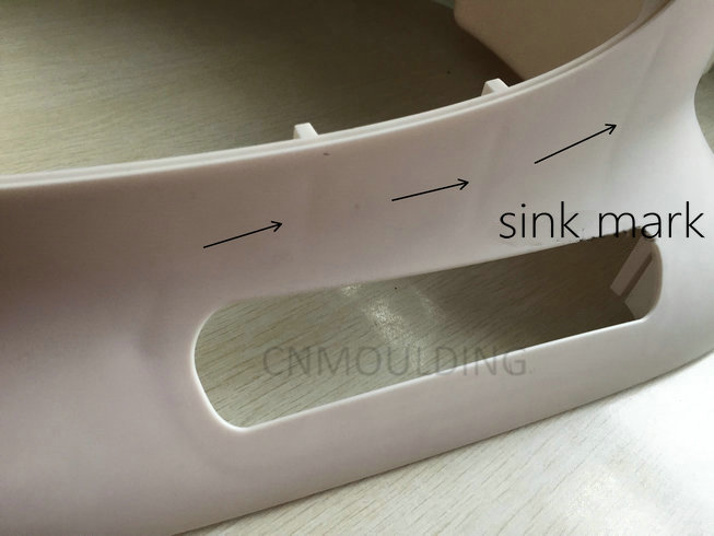
In plastic injection molding, sink marks are among the most common visual and structural defects. They appear as shallow depressions, dimples, or hollows on the surface of a molded part.
Understanding the root causes of sink marks—and knowing how to prevent them through proper part design and processing parameters—is critical to achieving high-quality production results.
What Causes Sink Marks?
A sink mark occurs during the cooling phase. When a plastic part is injected, the outer layer touching the cold mold steel solidifies first. However, the thicker core or inner material remains molten and cools much more slowly. As this inner core eventually solidifies and shrinks, it exerts a thermal contraction force, pulling the already-solidified outer skin inward and creating a depression.
Sink marks are most prevalent in thick sections, or directly behind structural features like ribs, bosses, and internal walls where material mass is concentrated.
Major Causes of Sink Marks
The formation of sink marks usually stems from three main categories: Part Design, Material Selection, and Processing Parameters.
1. Processing Parameters (Molding Conditions)
- Inadequate Holding Pressure or Time: Holding pressure packs extra material into the mold cavity to compensate for natural volumetric shrinkage. If the holding pressure is too low, or the holding time is too short (gate freezes off too early), the cavity will under-pack, causing the material to shrink excessively.
- Insufficient Cooling Time: If the cooling cycle is cut short, the part is ejected while its core is still soft and unstable, leading to post-ejection shrinkage.
- Excessive Melt Temperature: High melt temperatures increase the overall thermal expansion of the plastic, requiring more cooling time and leading to greater total shrinkage.
2. Part & Mold Design
- Excessive or Non-Uniform Wall Thickness: Thicker sections retain heat longer. If a part has sudden transitions from thin to thick walls, the thick areas will cool slower, making them prime targets for sink marks.
- Improper Gate Size or Location: If the gate is too small, it freezes before the part cavity can be fully packed. If the gate is located too far from the thickest section, pressure drops before it can adequately pack that dense area.
3. Material Properties
- High Material Shrinkage Rate: Semi-crystalline plastics (such as PP, PE, or Nylon/PA) exhibit much higher volumetric shrinkage rates during crystallization than amorphous plastics, making them inherently more prone to sinking.
Comprehensive Solutions to Prevent and Fix Sink Marks
To eliminate sink marks, engineers must optimize both the molding process and the physical layout of the part and mold.
1. Injection Molding Process Adjustments (Quick Fixes on the Shop Floor)
- Increase Packing/Holding Pressure and Time: Force more molten plastic into the cavity during the holding phase to make up for the volume lost during cooling.
- Lower Melt and Mold Temperatures: Reducing temperatures minimizes the total thermal contraction of the resin.
- Extend the Cooling Cycle: Ensure the core of the part is sufficiently solidified before the mold opens.
2. Tooling & Mold Design Optimization
- Optimize Gate Placement: Position the gate directly at or near the thickest section of the part. This ensures maximum packing pressure reaches the areas most vulnerable to sinking.
- Enlarge Gate and Runner Cross-Sections: Prevent premature gate freeze-off so that holding pressure remains effective throughout the cooling transition.
- Upgrade Mold Cooling Channels: Design conformal or highly efficient cooling circuits near thick zones to achieve uniform cooling rates across the entire mold insert.
3. Smart Part Design (The Ultimate Prevention)
- Maintain Uniform Wall Thickness: Always design parts with consistent wall structures.
- Follow the “Rib-to-Wall” Ratio: To avoid sink marks on the cosmetic surface opposite a rib, keep the rib thickness between 40% to 60% of the main nominal wall thickness.
- Utilize Coring and Ribbing: Instead of designing solid thick blocks, core out the excess material to create a hollowed section supported by thin reinforcing ribs.
Summary of Corrective Actions
| Action Type | Solution Strategy |
| On-Site Processing | Increase holding pressure • Extend holding time • Lower melt temperature • Extend cooling time |
| Mold Modification | Relocate gate to thick areas • Increase gate/runner size • Optimize cooling channel layout |
| Product Redesign | Implement uniform wall thickness • Reduce rib/boss thickness • Use coring to eliminate heavy mass |
By pairing robust Design for Manufacturing (DFM) practices with precise injection molding control, you can consistently eliminate sink marks and deliver pristine, high-tolerance plastic components.