
Engineering Guide: Managing Plastic Shrinkage in Precision Injection molding
For precision injection molded components, achieving tight dimensional tolerances requires a definitive strategy for managing molding shrinkage ($S$) and post-shrinkage. Because thermoplastics inherently expand under thermal load and contract during solidification, controlling this volumetric delta is the foundation of high-yield mass production.
At our facilities, we leverage advanced Design for Manufacturability (DFM) and empirical data aligned with DIN 16901 standards to guarantee that your final part dimensions match your print exactly.
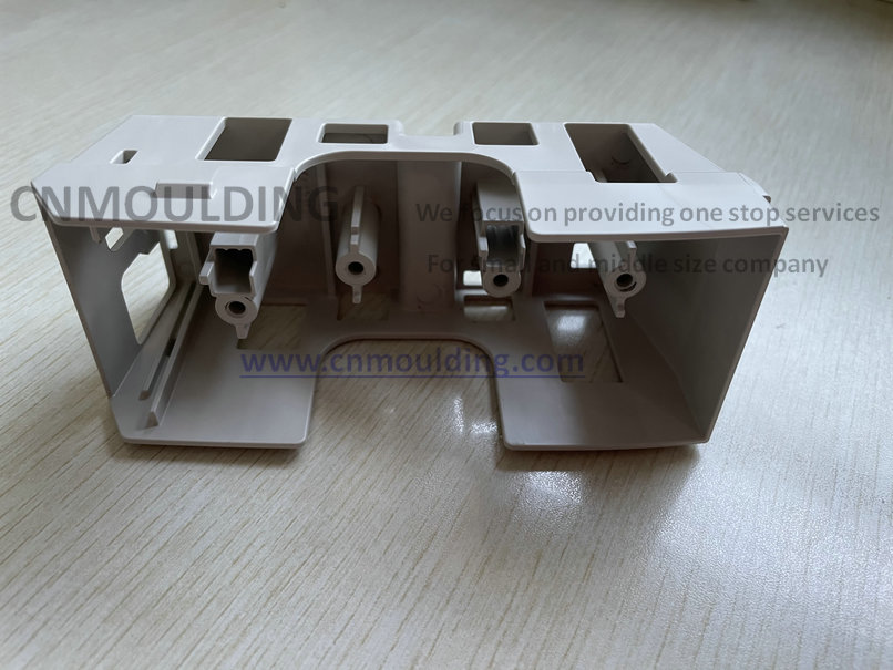
The Science of Volumetric Contraction: Forming vs. Post-Shrinkage
Total plastic part shrinkage is an aggregate of two distinct physical phases:
- Forming Shrinkage ($S$): The immediate volumetric contraction occurring inside the mold cavity during the cooling and injection/ejection phases.
- Post-Shrinkage & Environmental Expansion: Residual dimensional shifts that continue after ejection as internal molding stresses normalize over time.
While most semi-crystalline polymers continue to contract post-ejection due to ongoing crystallization, certain hygroscopic engineering plastics (e.g., Polyamides) absorb ambient moisture and swell over time. For instance, unfilled Nylon 610 can exhibit a dimensional increase of 2.0% at a 3.0% moisture content. Conversely, for dimensionally critical components, we often utilize Glass-Fiber Reinforced Polyamides (e.g., PA66-GF30), where the structural reinforcement mechanically restricts moisture uptake, limiting total volumetric swelling to a maximum of 0.3% even under fully saturated, high-humidity environments.
Our Standard QA Protocol: To isolate these dynamic variables and ensure absolute measurement reproducibility, all benchmark metrology inspections are executed exactly 24 hours post-ejection, after conditioning the molded parts in a climate-controlled laboratory stabilized at 23°C ± 0.1°C with a 50% ± 5% Relative Humidity (RH), strictly adhering to DIN 16901 guidelines.
Mitigating Shrinkage Variance: Engineering Solutions for 3 Critical Vectors
Plastic part shrinkage is never a fixed coefficient; it is a fluid range dictated by part geometry, mold design, and dynamic processing windows. Below is our engineering matrix for isolating and controlling these variances:
1. Part Geometry & Wall Thickness Management
- The Issue: Excessive wall thickness slows down heat dissipation, creating localized high-shrinkage zones that lead to internal voids and sink marks. Conversely, restrictive features like ribs, bosses, and internal cores create mechanical resistance that drastically reduces localized shrinkage. Furthermore, material located far away from the gate suffers severe pressure drop, resulting in less packing and higher shrinkage compared to areas near the gate.
- Our Solution: We enforce strict wall-thickness uniformity during initial DFM reviews. Where thickness transitions are unavoidable, we apply optimized cross-flow transitions and recalculate flow path lengths. To counteract the pressure drop across long flow lengths, we apply custom, localized mold cavity offsets to ensure the final product holds a uniform tolerance profile.
2. Advanced Mold Architecture & Gate Optimization
- The Issue: Undersized or poorly positioned gates freeze off prematurely, trapping the melt before the packing phase can compensate for volumetric contraction. Additionally, non-uniform mold surface temperatures cause uneven cooling rates across the part, generating differential shrinkage that forces the plastic component to warp or twist out of spec.
- Our Solution: We run comprehensive Moldflow Simulations to lock in the optimal gate type and location, ensuring the packing channel remains open until the nominal wall section solidifies. We integrate independent, multi-zone cooling loops—and implement Conformal Cooling Channels for highly complex cores—to maintain absolute thermal equilibrium across the mold faces, eliminating thermal-induced warpage.
3. Injection Molding Process Parameter Calibration
- The Issue: Fluctuations in hold pressures, melt thermal profiles, and injection velocities directly disrupt the polymer’s packing density, causing unpredictable part-to-part dimensional drift.
- Our Solution: We optimize processing windows utilizing Scientific Molding principles to establish a stable, repeatable molding cycle:
| Process Variable | Direct Impact on Part Shrinkage | Our Optimization Strategy |
|---|---|---|
| Holding Pressure | High Pressure = Higher Part Density = Lower Shrinkage | We maximize packing pressure and duration right up to the gate-freeze point to tightly pack the polymer molecules and minimize volumetric contraction. |
| Melt Temperature | High Melt Temp = Lower Viscosity = Better Pressure Transmission | We optimize barrel temperature profiles to lower melt viscosity, ensuring maximum holding pressure is transmitted into deep, restrictive cavity features to combat localized shrinkage. |
| Mold Temperature | High Mold Temp = Slower Cooling = Higher Shrinkage (Standard Parts) High Mold Temp = Lower Flow Resistance (Thin-Walled Parts) | For standard components, we control mold temperatures to govern crystalline growth. However, for thin-walled components, we intentionally maintain higher mold temperatures; this lowers the flow resistance of the melt, preventing premature freeze-off and allowing full packing pressure to reach the thinnest sections of the part to lock in precision dimensions. |
Our “Steel-Safe” Mold Machining Strategy
Because resin batches vary and real-world polymer contraction remains highly non-linear, calculating mold dimensions via formulas is only the baseline. To fully protect your tooling investment, we execute a disciplined Steel-Safe Tool Machining Protocol:
- Internal Cavities (Female Features): Machined toward the lower tolerance deviation limit (less steel removed). If the final plastic part shrinks less than predicted, we can safely remove more steel via EDM or precision CNC grinding to enlarge the cavity.
- Cores & Bosses (Male Features): Machined toward the upper tolerance deviation limit (more steel left on the tool). This leaves excess steel on the core, allowing us to machine it down (shave the steel) if the part’s internal openings or snap-fits need to be enlarged.
By combining rigorous DFM, empirical DIN 16901 data tracking, and a strict steel-safe machining execution, we eliminate the guesswork from tooling—delivering parts that hit your nominal tolerance targets on the very first tool trial (T1).